Tech/Engineering

Efficient Data Recovery | Unleashing the Potential of File-Level Restores - Part 2

Rakesh Sharma, Sr. Staff Software Engineer

In part 1 of this blog post, we learned about FLR, its significance, and the solution that we built to make VM file restores easy and less resource-intensive.

In part 2, we will discuss the improvements we made in the FLR restore process to achieve faster execution speeds.

But, before that, here’s the tech stack and key terms that we will use frequently throughout the blog.

Technology stack that we used

  • Language: Python

  • FUSE: User module implemented with Python
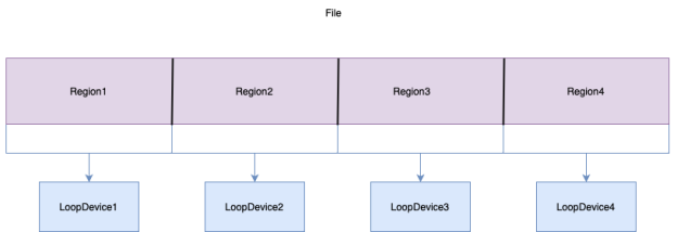
  • Loop Devices

Terminology

  • FLR: File-Level Restore.

  • Virtual disk: A virtual disk is a file that appears as a physical disk drive to the guest operating system. Virtual hard disk files store information, such as the operating system, program files, and data files.

  • Disk Offset: An offset into a disk is simply the character location within that disk, usually starting with 0. Thus, "offset 240" is the 241st byte in the disk.

  • File Offset: An offset into a file is simply the character location within that file, usually starting with 0. The important thing to note is that a File Offset is converted to a Disk Offset before the data can be read  – this conversion is done by the underlying FileSystem.

  • Target/Target VM: Used interchangeably to refer to a target virtual machine where data has to be restored.

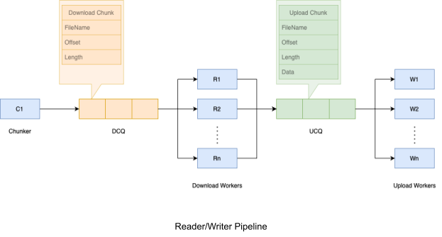
  • Download Chunk: Data at a particular file offset that is not yet downloaded/read from the cloud. It is defined by the tuple of filename, offset, and length:

    • Filename: The file to be read.

    • Offset: Denotes the location of the character within the filename of the file from where the data has to be read. Note that this is a file offset which is converted to disk offset by the mounted file system. 

    • Length: Length of data to be read starting from the offset. 

  • Upload Chunk: Data at a particular file offset that has been downloaded from the cloud but is not yet uploaded/written to the target VM. It is defined by the tuple of filename, offset, length, and data: 

    • Filename: The file to be written.

    • Offset: Denotes the location of the character within the filename from where the data has to be written. 

    • Length: Length of data to be written starting from the offset. 

    • Data: The data to be written.

Reader/Writer Pipeline

The InitiateFileTransferToGuest API reads from the source and writes to the target. However, the API does not provide any control over the following: 

  • Number of threads used to read/write data

  • How much data is read at once

  • How much data is written at once

Essentially, we don’t have any information about InitiateFileTransferToGuest API’s internals. However, we did know that it is not very performant, at least in our case. We wanted to have more control over how data is being read from the source and written to the target. 

To workaround this issue, we implemented our own reader/writer pipeline. To support this new implementation, we injected an executable in the target VM using InitiateFileTransferToGuest API. This executable starts a rest server in the target VM and exposes REST APIs to write data to a file. We will now be using this new API to write data to the target VM.

The Pipeline

There are two queues:

  1. Download Chunk Queue (DCQ): A FIFO queue for the download chunks

  2. Upload Chunk Queue (UCQ): A FIFO queue for the upload chunks

There are three groups of workers that work together on the above queues to read files from the cloud and write files to the Target VM.

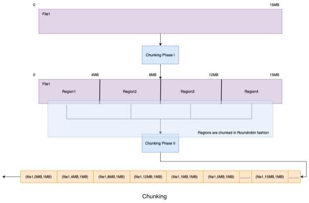
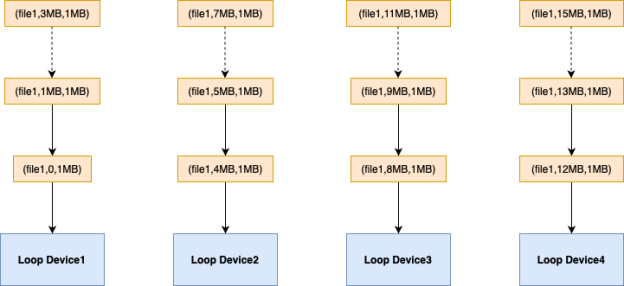
  1. Chunker: Divides a file into 1 MB Chunks and adds to DCQ (Download Chunk Queue). The last chunk of the file may be smaller than 1 MB.
  2. Download Workers: Pick up download chunks of the file from DCQ and issue read requests. Once the chunk has been downloaded, add it to UCQ.
  3. Upload Workers: Picks up upload chunks of the file from UCQ and uploads them to the target VM.
FLR3

This gave us more control over how files were being read from the source and written to the target. With this simple change, we were able to see 3x performance improvement.

Duplicate Loop Devices

In the original design, multiple readers per file attempted to read from a loop device. However, concurrent read requests were throttled at the loop device limiting performance improvement regardless of the number of readers. 

fl2 4

To address this limitation, we introduced the concept of duplicate loop devices. By creating multiple independent loop devices for the same backing file, we created additional access routes for reading the file. The new architecture looked like this:

FLR5

This approach distributed concurrent read requests across the duplicate loop devices, resulting in improved performance.

We ensured scalability by implementing the code to support horizontal scaling, allowing for the utilization of multiple loop devices by multiple readers.

Since the loop devices were mounted as read-only and we were performing read operations only, the risk of data corruption (which can occur with concurrent writes using duplicate loop devices) was eliminated.

This worked like magic and the performance improved many folds.

Now, let us understand the crucial components of this architecture in more detail.

The Chunker

Divides a large single file into logical regions where all regions except possibly the last one are equal in size and adds download chunks from these regions to the DCQ in a round-robin fashion. where

Number of logical regions = Number of loop devices

For example, a 16 MB file will be chunked as below with 4 loop devices:

  • Divide the file into 4 logical regions of 4 MB each (Phase I).

  • Chunk these regions concurrently and add download chunks to the DCQ in a round-robin manner (Phase II). This means adding one chunk from each region to DCQ and repeating. This ordering of chunks in DCQ is crucial to ensure that each loop device works on a different region of the file.

FLR6

Since chunking is faster than downloading or uploading, we have just a single chunker instead of multiple chunkers. It means that at most one file is chunked at a time. Chunking for the next file begins only after all the download chunks belonging to the current file are added to the DCQ.

Download Workers

The algorithm for downloading chunks of a file utilizes a round-robin approach to read chunks from multiple loop devices. When a chunk is selected from the DCQ, the DownloadWorker object interacts with a DataManager object to determine the loop device responsible for reading the chunk. The DataManager ensures that each loop device is used before cycling back to reuse a loop device again.

These two algorithms combined imply two important properties:

  1. Two consecutive download chunks in DCQ are never read from the same loop device.

  2. All chunks of a logical region are read from the same loop device.

For example, for the DCQ shown above, chunks will be downloaded in the following manner.

FLR7


As is evident from the above figure, each loop device is working on a completely different region of the file being downloaded.

The same can be visualized more clearly with the following diagram.

FLR8


Upload Workers 

These are the simplest group of workers. Each upload worker picks up an upload chunk from UCQ and invokes a REST API to transfer this chunk to the target VM.

Conclusion

With all of these improvements, we now get FLR performance of up to 90 GBPH with 4 Loop devices. When we increase the number of loop devices to 8, the performance improves almost linearly (up to 150 GBPH with 8 Loop Devices). 

Loop Devices Per Disk

Performance (GBPH)

1

20

4

90

8

150

When we use 8 loop devices instead of 4 per disk, the CPU utilization does not increase linearly.  The CPU usage increases only by a few percent. Hence, we are using 8 loop devices per disk in our production environment.

References 

loop(4) - Linux manual page
Filesystem in Userspace - Wikipedia